CCNAv7 – Introduction to Networks
(Same)
CCNA1 v7.0: ITN Practice PT Skills Assessment (PTSA) – TYPE 2
Type 2 (just different names devices)
ITN Practice Skills Assessment – Packet Tracer Answers
A few things to keep in mind while completing this activity:
- Do not use the browser Back button or close or reload any exam windows during the exam.
- Do not close Packet Tracer when you are done. It will close automatically.
- Click the Submit Assessment button in the browser window to submit your work.
Introduction
In this assessment, you will configure devices in an IPv4/IPv6 network. For the sake of time, you will not be asked to perform all configurations on all network devices as you may be required to do in a real network or other assessment. Instead, you will use the skills and knowledge that you have learned in the labs in this course to configure the Town Hall router. In addition, you will address the hosts on two LANs with IPv4 and IPv6 addresses and activate and address the management interface of the Administration Switch.
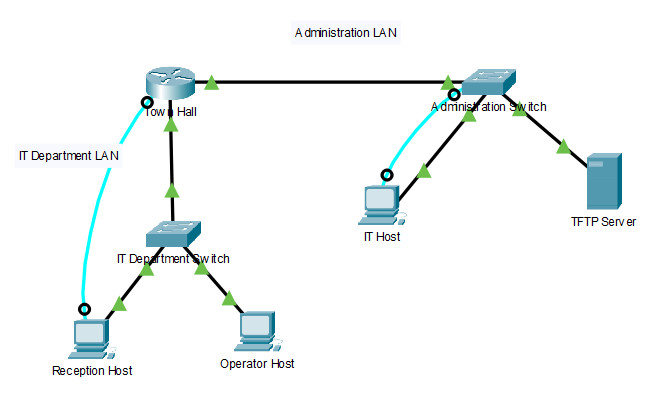
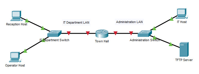
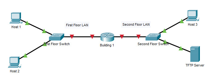
You will receive one of several topologies.
You are not required to configure the IT Department Switch, and you will not be able to access it in this practice skills assessment activity.
All IOS device configurations should be completed from a direct terminal connection to the device console. In addition, many values that are required to complete the configurations have not been given to you. In those cases, create the values that you need to complete the requirements. For values that have been supplied to you, they must be entered exactly as they appear in order for you to get full credit for your configuration.
You will practice and be assessed on the following skills:
- Configuration of initial IOS device settings
- Design and calculation of IPv4 addressing
- Configuration of IOS device interfaces including IPv4 and IPv6 addressing when appropriate
- Addressing of network hosts with IPv4 and IPv6 addresses
- Enhancing device security, including configuration of the secure transport protocol for remote device configuration
- Configuration of a switch management interface
Requirements by device:
Town Hall router:
- Configuration of initial router settings
- Interface configuration and IPv4 and IPv6 addressing
- Device security enhancement or device hardening
- Secure transport for remote configuration connections as covered in the labs
- Backup of the configuration file to a TFTP server
Administration Switch:
- Enabling basic remote management by Telnet
- PC and Server hosts:
- IPv4 full addressing
- IPv6 addressing
Addressing Table
(or Building 1) | G0/0 | 192.168.1.126 | 255.255.255.224 | N/A |
| 2001:DB8:ACAD:A::1/64 | N/A | |||
| G0/1 | 192.168.1.158 | 255.255.255.240 | N/A | |
| 2001:DB8:ACAD:B::1/64 | N/A | |||
| Link Local | FE80::1 | N/A | ||
(or Second Floor Switch) | Vlan 1 | 192.168.1.157 | 255.255.255.240 | 192.168.1.158 |
| N/A | N/A | N/A | ||
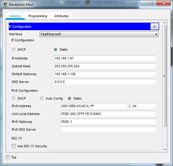
(or Host 1) | NIC | 192.168.1.97 | 255.255.255.224 | 192.168.1.126 |
| 2001:DB8:ACAD:A::FF | FE80::1 | |||
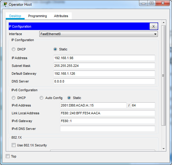
(or Host 2) | NIC | 192.168.1.98 | 255.255.255.224 | 192.168.1.126 |
| 2001:DB8:ACAD:A::15 | FE80::1 | |||
(or Host 3) | NIC | 192.168.1.145 | 255.255.255.240 | 192.168.1.158 |
| 2001:DB8:ACAD:B::FF | FE80::1 | |||
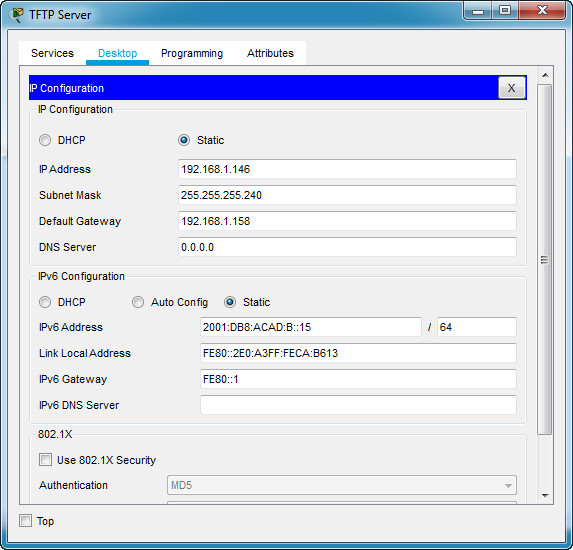
| NIC | 192.168.1.146 | 255.255.255.240 | 192.168.1.158 | |
| 2001:DB8:ACAD:B::15 | FE80::1 | |||
Instructions
Step 1: Determine the IP Addressing Scheme.
Design an IPv4 addressing scheme and complete the Addressing Table based on the following requirements. Use the table to help you organize your work.
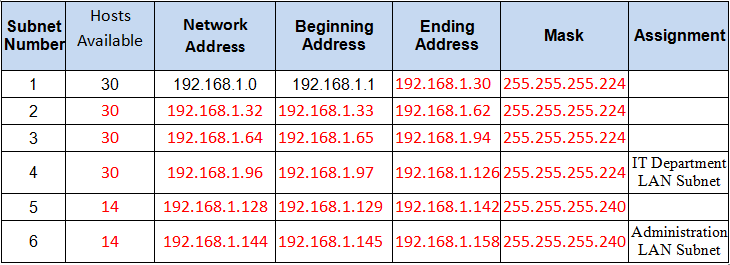
- a.Subnet the 192.168.1.0/24 network to provide 30 host addresses per subnet while wasting the fewest addresses.
- b.Assign the fourth subnet to the IT Department LAN.
- c.Assign the last network host address (the highest) in this subnet to the G0/0 interface on Town Hall.
- d.Starting with the fifth subnet, subnet the network again so that the new subnets will provide 14 host addresses per subnet while wasting the fewest addresses.
- e.Assign the second of these new 14-host subnets to the Administration LAN.
- f.Assign the last network host address (the highest) in the Administration LAN subnet to the G0/1 interface of the Town Hall router.
- g.Assign the second to the last address (the second highest) in this subnet to the VLAN 1 interface of the Administration Switch.
- h.Configure addresses on the hosts using any of the remaining addresses in their respective subnets.
Step 2: Configure the Town Hall Router.
a. Configure the Town Hall router with all initial configurations that you have learned in the course so far:
b. Configure the two Gigabit Ethernet interfaces using the IPv4 addressing values you calculated and the IPv6 values provided in the addressing table.
- Reconfigure the link local addresses to the value shown in the table.
- Document the interfaces in the configuration file.
Step 3: Configure the Administration Switch.
Configure Administration Switch for remote management over Telnet.
- a. Use the IPv4 addressing from Step 1 and the IPv6 addressing values provided in the addressing table to configure all host PCs with the correct addressing.
- b. Use the router interface link-local address as the IPv6 default gateways on the hosts.
- c. Complete the configuration of the TFTP server using the IPv4 addressing values from Step 1 and the values in the addressing table.
Answers – Passed 100% Score (for both types)

Town Hall router (or Building 1 Router)
Use line console to connect Reception Host (or Host 1) and Town Hall router (or Building 1). On Reception Host (or Host 1), go to “Desktop Tab” –> choice “Terminal”
en
conf terminal
hostname Middle
enable secret class12345
service password-encryption
banner motd $This is Router$
security passwords min-length 10
login block-for 120 attempts 2 within 30
no ip domain-lookup
ip domain-name ITExamAnswers.net
crypto key generate rsa
1024

line console 0
password cisco12345
login
logging synchronous
exec-timeout 60
exit

line vty 0 4
password cisco12345
transport input ssh
login local
logging synchronous
exec-timeout 60
exit

line aux 0
password cisco12345
login
logging synchronous
exec-timeout 60
exit

ip ssh version 2
ip ssh time-out 120
username netadmin privilege 15 secret Cisco_CCNA5

interface g0/0
ip address 192.168.1.126 255.255.255.224
description First Floor LAN
ipv6 address 2001:DB8:ACAD:A::1/64
ipv6 address fe80::1 link-local
no shutdown
exit

interface g0/1
ip address 192.168.1.158 255.255.255.240
description Second Floor LAN
ipv6 address 2001:DB8:ACAD:B::1/64
ipv6 address fe80::1 link-local
no shutdown
exit
ipv6 unicast-routing
exit
write
Administration Switch (or Second Floor Switch)
Use line console to connect IT Host (or Host 3) and Administration Switch (or Second Floor Switch). On IT Host (or Host 3), go to “Desktop Tab” –> choice “Terminal”
enable
conf terminal
enable secret class12345
service password-encryption
banner motd $Second Floor Switch$
no ip domain-lookup

line console 0
password cisco12345
login
logging synchronous
exec-timeout 60
exit

line vty 0 15
password cisco12345
login
logging synchronous
exec-timeout 60
exit

interface vlan 1
ip address 192.168.1.157 255.255.255.240
no shutdown

ip default-gateway 192.168.1.158
exit
write
Town Hall router (or Building 1)
copy running-config tftp:
192.168.1.146